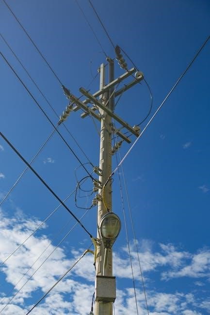
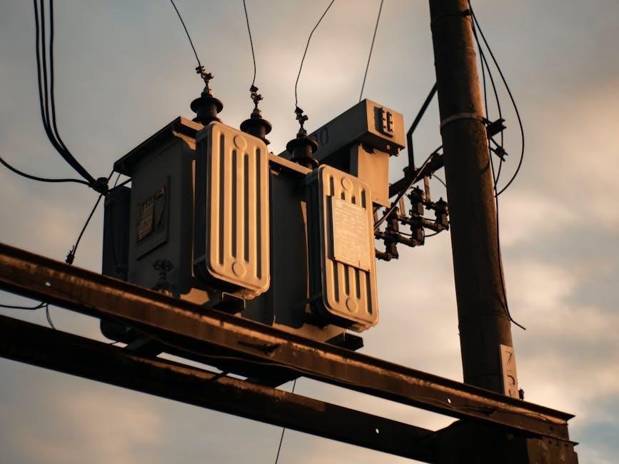
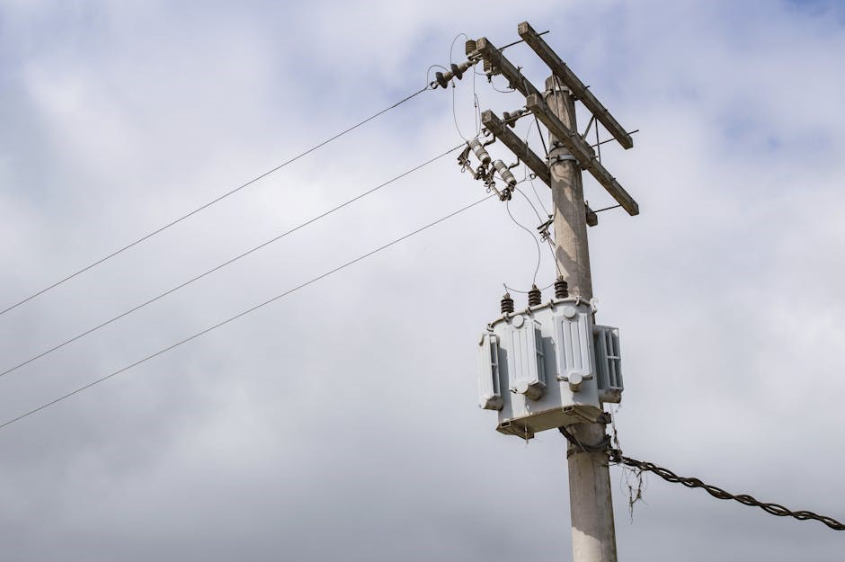
Transformer wiring is a fundamental aspect of electrical systems‚ ensuring safe and efficient power distribution. This guide provides essential insights and step-by-step instructions for proper transformer wiring‚ focusing on safety‚ efficiency‚ and compliance with electrical standards.
Understanding the Basics of Transformers
A transformer is an electrical device that transfers energy between circuits through electromagnetic induction. It consists of primary and secondary windings wound around a magnetic core. The primary winding receives the input voltage‚ while the secondary winding delivers the output voltage. Transformers are used to step up or step down voltages‚ ensuring compatibility between power sources and loads. They operate on the principle of mutual induction‚ where a changing current in one winding induces voltage in the other. Understanding transformer basics is crucial for safe and efficient wiring‚ as improper connections can lead to system failures or safety hazards. Familiarity with transformer types‚ such as single-phase or three-phase‚ is also essential for selecting the right unit for specific applications.
Importance of Proper Transformer Wiring
Proper transformer wiring is essential for ensuring safety‚ efficiency‚ and reliability in electrical systems. Incorrect wiring can lead to short circuits‚ equipment damage‚ or even dangerous electrical fires. Correct connections prevent voltage mismatches‚ reducing the risk of overloading and ensuring optimal performance. Compliance with safety standards like NFPA 70E and CSA Z462 is critical to safeguard personnel and equipment. Proper wiring also minimizes energy losses‚ reducing operational costs and enhancing system lifespan. It ensures consistent power delivery‚ crucial for sensitive devices and industrial applications. Adhering to wiring best practices protects both the transformer and connected loads‚ maintaining overall system integrity and performance. Precision is key to avoiding potential hazards and ensuring reliable operation.
Understanding Transformer Wiring Diagrams
Understanding transformer wiring diagrams is crucial for guiding installation‚ troubleshooting‚ and ensuring safe and efficient electrical connections. They provide a clear visual representation of windings‚ circuits‚ and connections.
Reading Primary and Secondary Windings
Reading primary and secondary windings is essential for understanding transformer operation. The primary winding receives the input AC voltage‚ while the secondary winding delivers the transformed output voltage. In diagrams‚ these windings are typically labeled with distinct identifiers‚ such as “H1‚ H2” for primary and “X1‚ X2” for secondary. Correctly identifying these terminals ensures proper connections and prevents phase mismatches. Understanding polarity‚ often marked by dots or arrows‚ is crucial for maintaining the correct current flow direction. Always refer to the transformer’s wiring diagram to verify connections‚ ensuring safe and efficient operation of the electrical system.
Interpreting Transformer Schematics
Interpreting transformer schematics involves understanding the symbols and connections. Transformers are represented by two coils‚ primary and secondary‚ with polarity indicated by dots or arrows. For three-phase transformers‚ delta and star configurations are common. Terminal labels like H1‚ H2 and X1‚ X2 guide connections. Identify windings‚ taps‚ and configurations to wire correctly. Ensure polarity matches for proper phase relationships. This knowledge aids in accurate wiring‚ ensuring safe and efficient transformer operation.
Step-by-Step Transformer Wiring Guide
Wiring a transformer involves identifying terminals‚ connecting primary and secondary windings‚ and ensuring correct polarity; Follow diagrams‚ use insulated tools‚ and test connections for safety and efficiency.
Single-Phase Transformer Wiring Process
Wiring a single-phase transformer requires careful attention to detail to ensure safe and efficient operation. Begin by identifying the primary and secondary terminals‚ typically labeled as “H1” and “H2” for the primary side‚ and “X1” and “X2” for the secondary side. Next‚ connect the primary winding to the power source‚ ensuring the correct voltage rating is matched. Then‚ connect the secondary winding to the load‚ making sure the polarity is maintained to prevent any phase shift. Use insulated tools and follow safety guidelines to avoid electrical shock. Finally‚ test the connections with a multimeter to verify proper voltage output before powering up the system. This step-by-step process ensures reliability and compliance with electrical standards.
Three-Phase Transformer Wiring Process
Three-phase transformer wiring is more complex than single-phase‚ requiring precise connections to maintain balanced power distribution. Begin by identifying the primary and secondary terminals‚ typically labeled as “H1‚ H2‚ H3” for the primary and “X1‚ X2‚ X3” for the secondary. Connect the primary winding to the three-phase power source‚ ensuring the correct voltage and phase sequence. Next‚ connect the secondary winding to the load‚ maintaining the same phase sequence to avoid voltage imbalances. Use appropriate PPE and follow NFPA 70E guidelines for safety. Finally‚ test the connections with a multimeter to verify proper voltage and phase alignment before energizing the system; This ensures efficient and safe three-phase power distribution.

Safety Guidelines for Transformer Installation
Adhere to NFPA 70E and CSA Z462 standards‚ ensuring proper PPE use. Always de-energize the system before starting work and use insulated tools to prevent electrical hazards.
NFPA 70E and CSA Z462 Compliance
Compliance with NFPA 70E and CSA Z462 is critical for ensuring electrical safety during transformer installation. These standards outline requirements for personal protective equipment (PPE)‚ arc flash protection‚ and safe work practices. NFPA 70E provides guidelines for electrical safety in the workplace‚ while CSA Z462 specifies Canadian standards for workplace electrical safety. Both emphasize the importance of risk assessments‚ proper PPE‚ and de-energizing systems before work begins. Adhering to these standards minimizes the risk of electrical hazards‚ ensuring a safe working environment for technicians and engineers. Always follow these guidelines to maintain compliance and protect personnel during transformer wiring and installation processes.
Use of Personal Protective Equipment (PPE)
The use of Personal Protective Equipment (PPE) is essential for ensuring safety during transformer wiring and installation. PPE includes arc-rated clothing‚ insulating gloves‚ safety glasses‚ and hard hats. These items protect against electrical arcs‚ shocks‚ and flying debris. Insulated tools‚ such as screwdrivers and pliers‚ should also be used to prevent direct contact with live circuits. Always conduct a pre-use inspection of PPE to ensure it is in good condition and rated for the voltage levels involved. Proper PPE usage significantly reduces the risk of injury and is a critical component of a safe working environment when handling electrical systems.

Transformer Installation Requirements
Proper transformer installation requires careful consideration of load requirements‚ nominal power selection‚ and correct terminal connections. Ensure compliance with safety standards and local electrical codes for reliable operation.

Load Requirements and Nominal Power Selection
Accurate determination of load requirements is critical for selecting the appropriate transformer size. Calculate the total voltage‚ current‚ and power needed for the connected devices. Ensure the transformer’s nominal power rating matches or exceeds the calculated load to prevent overload. Consider future expansion needs to avoid undersizing. Proper selection ensures efficient operation‚ reduces energy losses‚ and minimizes the risk of overheating. Always comply with NFPA 70E and CSA Z462 standards for electrical safety. Correct load assessment and nominal power selection are essential for reliable performance and long-term durability of the transformer. This step ensures the system operates safely and efficiently under specified conditions.
Correct Polarity and Terminal Connections
Ensuring correct polarity and terminal connections is vital for transformer operation. Misconnections can lead to malfunction or safety hazards. Identify primary and secondary terminals‚ typically labeled as input and output sides. Connect primary terminals to the power source and secondary terminals to the load. Maintain proper phase sequencing for three-phase transformers to avoid current imbalances. Use a multimeter to verify terminal configurations before energizing. Always refer to the transformer’s wiring diagram for specific instructions. Correct polarity ensures the transformer operates efficiently and safely‚ preventing damage to equipment or risk of electrical shock. Adhere strictly to manufacturer guidelines for terminal connections to maintain system integrity and performance.

Common Transformer Wiring Configurations
Common transformer wiring configurations include 480V to 120V and 480V to 240V setups‚ frequently used in industrial and commercial applications. These configurations ensure safe and efficient power conversion‚ adhering to specific wiring diagrams for optimal performance and compliance with electrical standards.
480V to 120V Transformer Wiring
Wiring a 480V to 120V transformer involves connecting the primary terminals to a 480V supply and the secondary terminals to a 120V load. Primary windings are typically labeled as H1 and H2‚ while secondary windings are marked as X1 and X2. Proper connections ensure safe and efficient step-down voltage conversion. Follow the wiring diagram to connect terminals correctly‚ using insulated tools and adhering to NFPA 70E standards. Ensure all connections are secure and insulated to prevent short circuits. Testing the output voltage with a multimeter before energizing the circuit is recommended for safety and accuracy.
480V to 240V Transformer Wiring
Wiring a 480V to 240V transformer involves connecting the primary terminals to a 480V three-phase supply and the secondary terminals to a 240V load. The primary windings (H1‚ H2‚ H3) connect to the 480V source‚ while the secondary windings (X1‚ X2‚ X3) deliver 240V output. Ensure proper phase sequencing and polarity to maintain balanced current flow. Use a multimeter to verify voltage levels before energizing the circuit. Follow the wiring diagram and safety guidelines‚ such as NFPA 70E‚ to prevent electrical hazards. Secure all connections tightly and insulate them to avoid short circuits. Testing the output voltage ensures safe and efficient operation.

Troubleshooting Common Wiring Issues
Common transformer wiring issues include open circuits‚ short circuits‚ or phase mismatches. Use a multimeter to diagnose faults and ensure proper terminal connections for safe operation.
Identifying Faults in Transformer Wiring
Identifying faults in transformer wiring requires careful inspection and testing. Common issues include open circuits‚ short circuits‚ or phase mismatches; Use a multimeter to measure resistance and voltage‚ ensuring proper connections. Check for signs of overheating‚ burn marks‚ or unusual noises. Verify polarity and terminal connections match the wiring diagram. Incorrect wiring can lead to reduced efficiency or complete system failure. Always disconnect power before testing and ensure compliance with safety standards. Consulting the transformer’s schematic diagram can help pinpoint faults quickly. Regular maintenance and inspections are crucial to prevent and identify wiring issues early‚ ensuring reliable operation and safety.
Diagnosing and Resolving Connection Problems
Diagnosing connection issues in transformer wiring involves systematic troubleshooting. Start by reviewing the wiring diagram to ensure all connections match specifications. Use a multimeter to test for continuity and voltage drop across terminals. Check for loose connections‚ corroded terminals‚ or damaged wires‚ which can cause intermittent faults. Verify phase sequencing in three-phase systems to prevent improper configuration. If a short circuit is detected‚ isolate the transformer and inspect for internal damage. Resolve issues by tightening connections‚ replacing faulty components‚ or rewiring as needed. Always follow safety protocols and manufacturer guidelines to ensure reliable operation and prevent future problems.
Tools and Materials Needed
A multimeter‚ insulated tools‚ and copper wires are essential. Ensure you have PPE‚ including gloves and safety glasses‚ along with appropriate insulation materials for secure connections.
Essential Tools for Transformer Wiring
Essential tools for transformer wiring include a multimeter for voltage and current measurements‚ insulated screwdrivers‚ and pliers for safe handling. A wire stripper is needed for preparing cables‚ while crimping tools ensure secure connections. A circuit tester helps verify live wires‚ and a torque wrench is crucial for tightening terminals properly. Safety gear like gloves and safety glasses is mandatory to prevent accidents. Additionally‚ a ladder or step stool may be necessary for accessing high-mounted transformers. Always use tools rated for the voltage and current levels involved to ensure safety and reliability during the wiring process.

Recommended Materials for Safe Installation
Transformer installation requires high-quality materials to ensure safety and efficiency. Key materials include insulated copper wires for minimizing resistance and heat-resistant cables for high-voltage applications. Terminal lugs and connectors should be appropriately rated to handle the current. Circuit breakers and fuses are essential for overload protection. High-voltage bushings and insulating tapes prevent arcing and ensure proper insulation. Steel enclosures are recommended to protect transformers from environmental factors and provide additional safety. Additionally‚ heat sinks can be used to manage temperature effectively. Always choose materials compliant with NFPA 70E and CSA Z462 standards for optimal performance and safety.
